When working with sheet metal a gauge table in solidworks can be used to ensure the correct thickness is chosen for your selected material along with the manufacturing properties as well.
Edit sheet metal materia gauce.
Video how to change sheet metal thickness in solid edge st7.
Sheet metal gauge size chart gauge or gage sizes are numbers that indicate the thickness of a piece of sheet metal with a higher number referring to a thinner sheet.
Extremely thin sheets are considered foil or leaf and pieces thicker than 6 mm 0 25 in are considered.
Sheet metal gauge is based on the weight of the sheet therefore a sheet of two different materials with the same thickness may have different gauge numbers.
Sheet metal is metal formed by an industrial process into thin flat pieces.
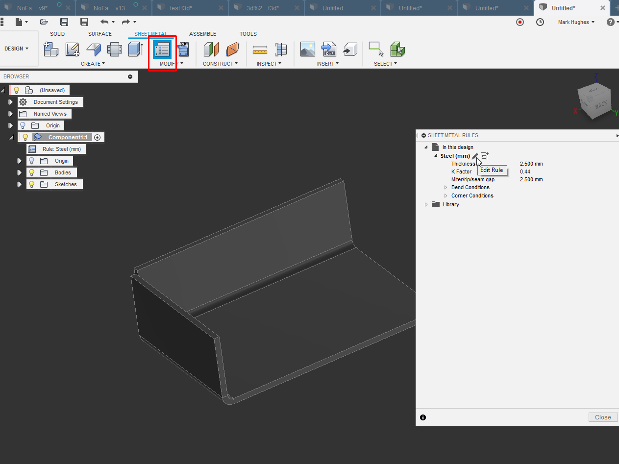
You can also select a material type unfolding rule and sheet thickness that is different from the value specified in the sheet metal rule.
The equivalent thicknesses differ for each gauge size standard which were developed based on the weight of the sheet for a given material.
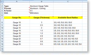
Sheet metal gauge bend tables store properties for a designated material.
We will start by creating a simple sheet metal design with a three line sketch.
A single table lets you associate a bend allowance bend radius or k factor with any combination of thickness bend radius and material.
Thicknesses can vary significantly.
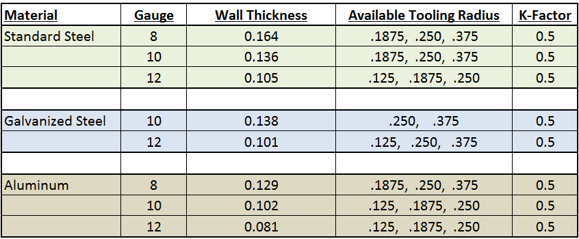
Our sheet metal design will use the following specifications.
Simple three line sketch to test our sheet metal gauge tables.
Solidworks 2016 sheet metal gauges may 2016 duration.
We are now ready to use these sheet metal gauge tables.
To help this blog will explain the gauge system and features a sheet metal gauge chart.
Access the style and standard.
10ga aluminum u channel with the dimensions 1 5 x 6 x 10 inches long.
Use the sheet metal defaults dialog box to change the options and parameters defined by the selected sheet metal rule for the active sheet metal part.


